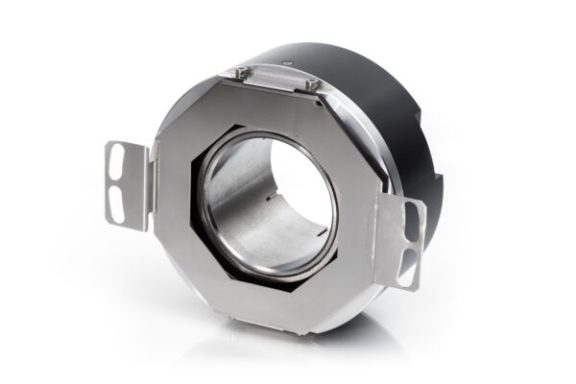


Photoelectric Rotary Encoder A58HE1
Photoelectric Rotary Encoder A58HE1 for hollow shafts has an external flexible coupling and
is the main feature that distinguishes it from other similar encoders.
It can produce up to 108,000 output pulses per revolution and has
different versions of output signals available: 11 μApp, 1Vpp, TTL or HTL.
- ELECTRICAL DATA:
| A58HE1-A 11 µApp | A58HE1-AV 1 Vpp | A58HE1-F TTL; HTL | |
| Supply voltage | +5 V ± 5% | +5 V ± 5% | +5 V ± 5%; +(10 to 30) V |
| Max. supply current (without load) | 80 mA | 120 mA | 120 mA |
| Light source | LED | LED | LED |
| Incremental signals | Two sinusoidal I1 and I2 Amplitude at 1 kΩ load: – I1 = 7-16 µA
– I2 = 7-16 µA |
Differential sine +A/-A and +B/-B Amplitude at 120 Ω load:
– A = 0.6-1.2 V – B = 0.6-1.2 V |
Differential square-wave U1/U1 and U2/U2. Signal levels at 20 mA load current:
– low (logic ”0”) < 0.5 V at UP=+5 V – low (logic ”0”) < 1.5 V at UP=10 to 30 V – high (logic ”1”) > 2.4 V at UP=+5 V – high (logic ”1”) > (UP-2) V at UP=10 to 30 V |
| Reference signal | One quasi-triangular I0 peak per revolution. Signal magnitude at 1 kW load:
– I0 = 2-8 µA (usable component) |
One quasi-triangular +R and its complementary -R per revolution. Signals magnitude at 120W load
– R = 0.2-0.8 V (usable component) |
One differential square-wave U0/U0 per revolution. Signal levels at 20 mA load current:
– low (logic “0”) < 0.5 V at UP=+5 V – low (logic “0”) < 1.5 V at UP=10 to 30 V – high (logic “1”) > 2.4 V at UP=+5 V – high (logic “1”) > (UP-2) V at UP=10 to 30 V |
| Maximum operating frequency | (-3 dB) > 160 kHz | (-3 dB) > 160 kHz | (160 x k) kHz, k-interpolation factor |
| Direction of signals | I 2 lags I1 for clockwise rotation (viewed from shaft side) | +B lags +A for clockwise rotation (viewed from shaft side) | U2 lags U1 with clockwise rotation (viewed from shaft side) |
| Maximum rise and fall time | – | – | < 0.5 µs |
| Standard cable length | 1 m, without connector | 1 m, without connector | 1 m, without connector |
| Maximum cable length | 5 m | 25 m | 25 m |
MECHANICAL DATA:
| Line number on disc (z) | 100; 250; 500; 600 800; 1000; 1024; 1125; 1250; 1500; 2000; 2048; 2500; 3000; 3600; 4000; 5000; 9000; 10800 |
| Number of output pulses per revolution | 100-108000 |
| Maximum shaft speed | 10000 rpm |
| Maximum shaft load |
axial: 0.5 mm |
| Accuracy (T1 -period of lines on disc in arc. sec) | ±0.1T1 arc. sec |
| Starting torque at 20°C | ≤ 0.025 Nm |
| Rotor moment of inertia | < 1.5 x 10⁻⁴ kgm2 |
| Protection ( IEC 529) | IP64 |
| Protection from shaft side ( IEC 529) | IP64 |
| Maximum weight without cable | 0.3 kg |
| Operating temperature | -10…+70°C |
| Storage temperature | -30…+80°C |
| Maximum humidity (non-condensing) | 98 % |
| Permissible vibration (55 to 2000 Hz) | ≤ 100 m/s² |
| Permissible shock (11 ms) | ≤ 1000 m/s² |